
And more importantly, it increases the safety of the children. I used a hot food box because preventing water heat resistant and very economical. But he embarrassed every time, friends to tease. The principle of this circuit, I built the bicycle tail light flashing for my son.

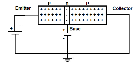
the circuit working will repeat loop in like this. It turns off, LED2 goes out.Īfter that Q1 will turn on and LED1 to grow up again. The C1 begins to charge until full, VBE of Q2 is lower than 0.7V. Next Q2 start working, LED2 also grows more brightly. At the same time, some current will flow through LED2, R4, and to charge into C2 until full. It makes the current to flow through LED1, R1, and the collector-emitter of Q1. To begin with, suppose that the Q1 run first. It will work only on the negative voltage. It is a PNP-transistor that works as a switch. I hope you understand it easily.įirst of all, suppose that Q1 works first. Note: It may incorrect in full academic principles. This circuit is so easy, learning how it works is interesting. How does Dual LED flashing light circuit work? When they have different values, one LED will stay on longer than the other. How does NE555 timer circuit works | Datasheet | Pinoutįinally, the Flash rate is easily changed simply by changing one, or both, of the timing capacitors C1 and C2.Basic H-bridge motor driver circuit using bipolar transistor.How 741 Op-Amp Power supply Circuit works.

They control the gain of amplifiers.Īnd importantly, they increase the time required to charge capacitors and speed up the discharge of capacitors. Third, R3 and R4 make a bias current to the base of transistors to conduct current. In lower resistance will be high current and high lighting. If you use a 9V battery, you can use up to 1K, 3mm LEDs. They are like switches on-off to drive two LEDs. I just want to see you use it in an easy way.įirst, Both Q1 and Q2 are general PNP transistors such as 2N3906,2N2907, BC558, etc.


 0 kommentar(er)
